AOA v2 Build Instructions
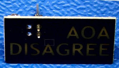
Thank you for purchasing an AOA DISAGREE v2 KIT!
Included in your kit should be the following:
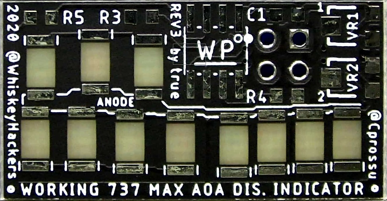
- 2x AOA DISAGREE REV3 boards
- 2x WP CHIP
- 6x resistors
- 2x capacitors
- 25x LEDs
- 4 sets dual pin header
- 2x retention lanyard
Required tools for assembly:
- Intermediate soldering experience
- Ability and willingness to solder in confined spaces, and in non-standard ways
- Soldering iron, solder
- Flux
- Bent-nose, fine tip SMD tweezers
Build instruction notes:
These build instructions assume you are right handed. Modify as needed if you are left handed.
Build instructions:
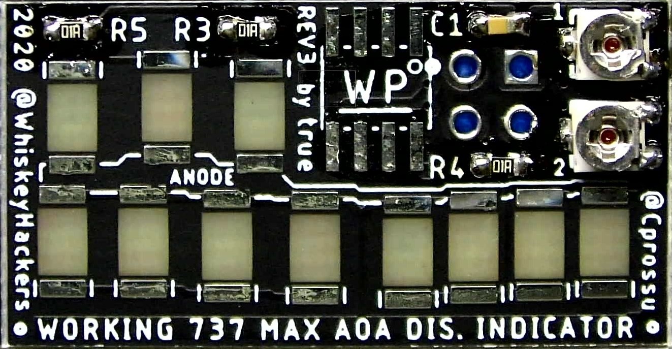
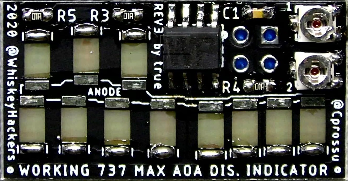
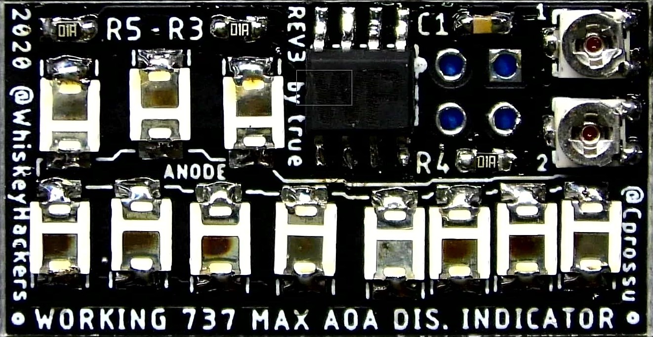
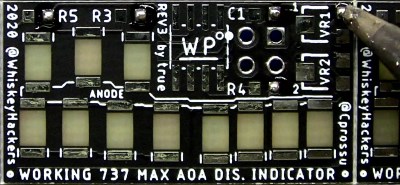
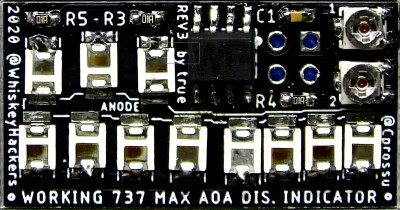
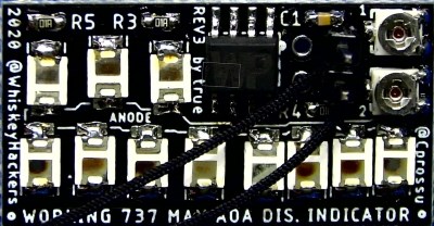
1. Set up your board for assembly.
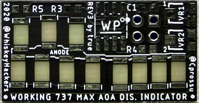
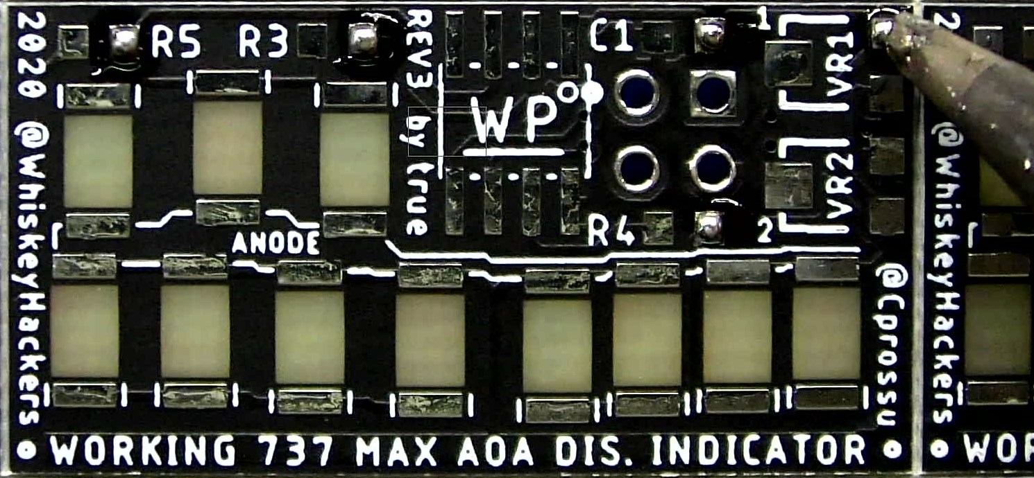
2. Tin the right pads of R3, R4, R5, C1. Tin the top right pads of VR1 and VR2.
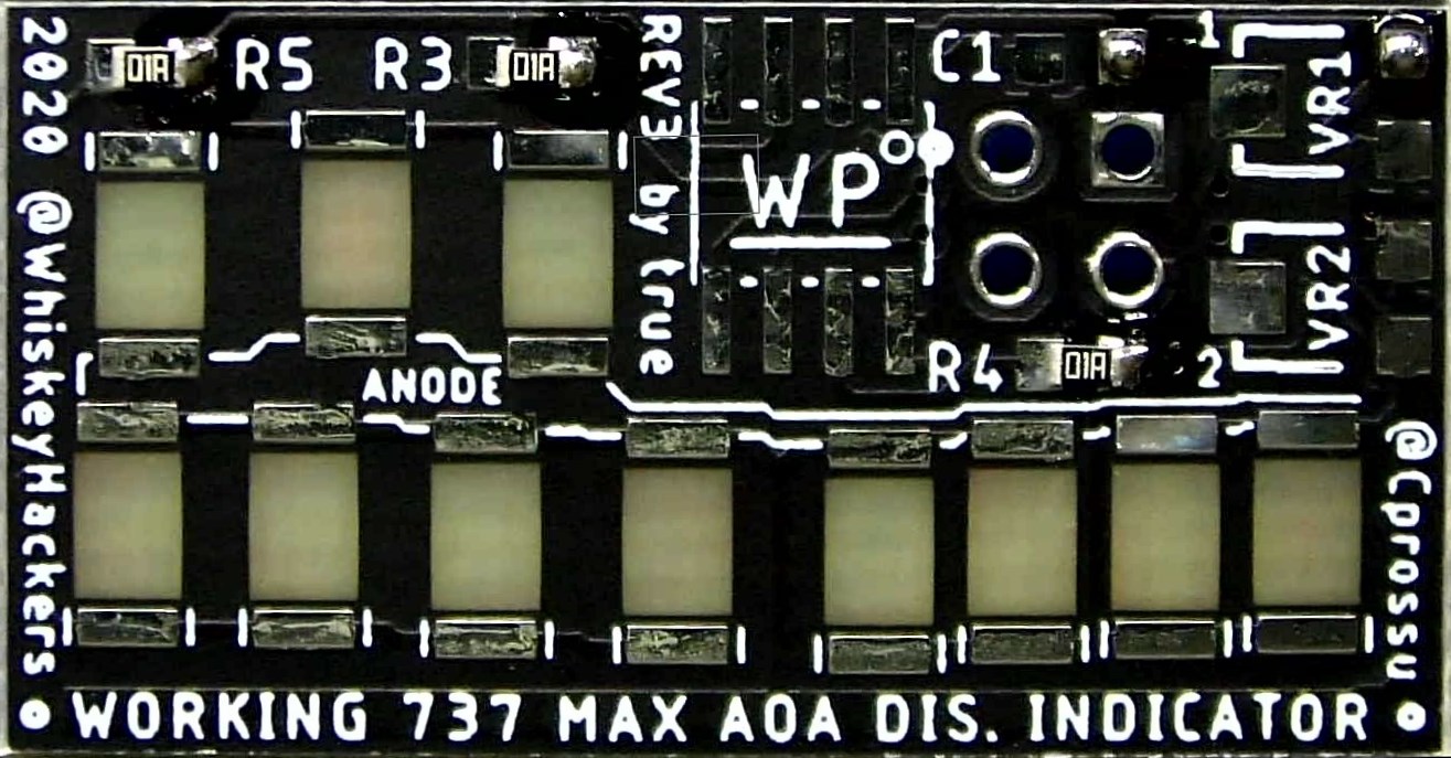
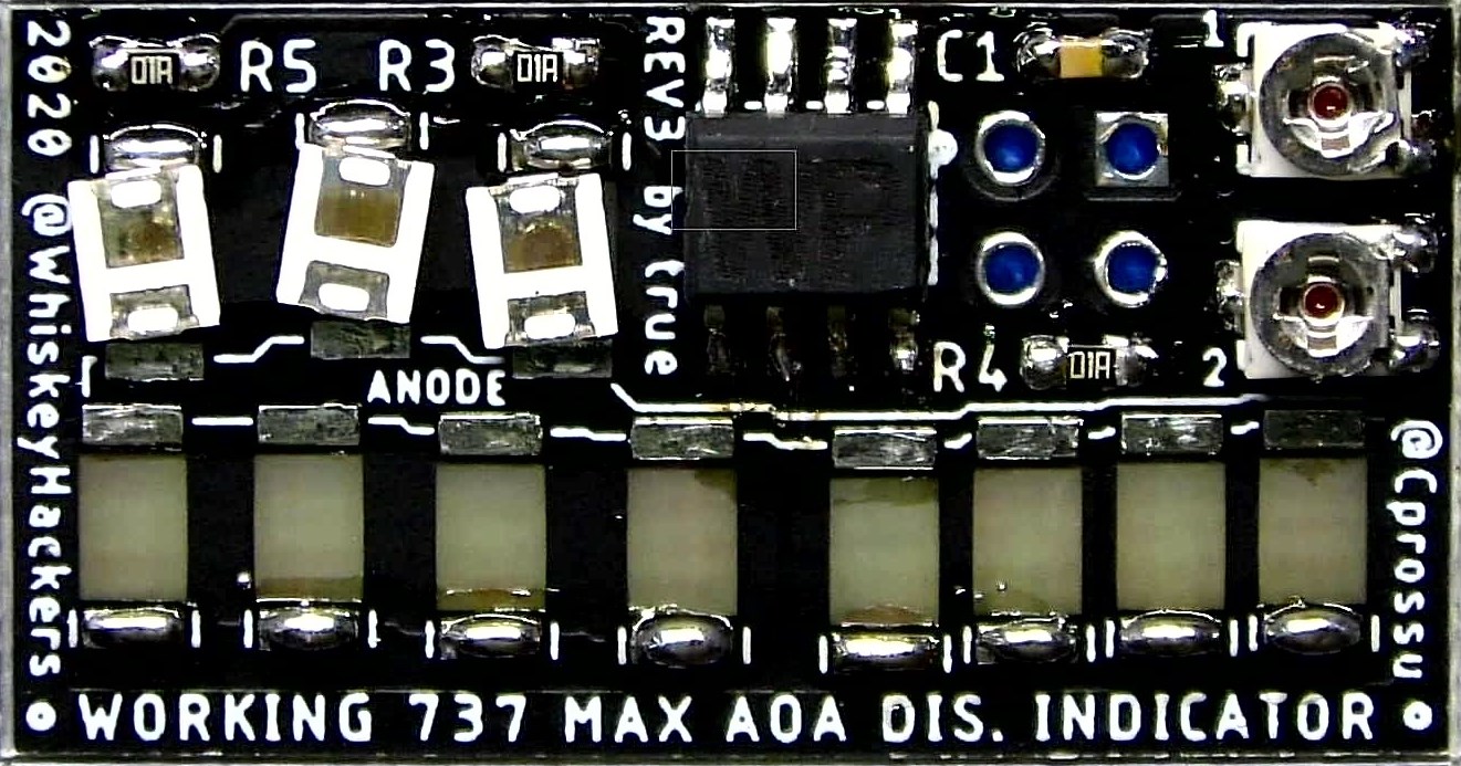
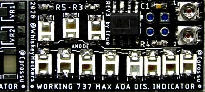
3.   Solder resistors to tinned pads with standard SMD soldering technique.
     Resistors will be ~50Ω in high-bright kits and 100Ω in standard-bright kits.

4. Solder capacitor to tinned pad with standard SMD soldering technique.
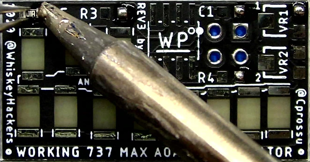
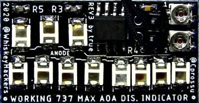
5. Flux variable resistor, WP CHIP, and LED pads.
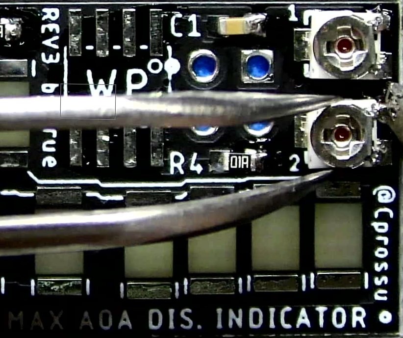
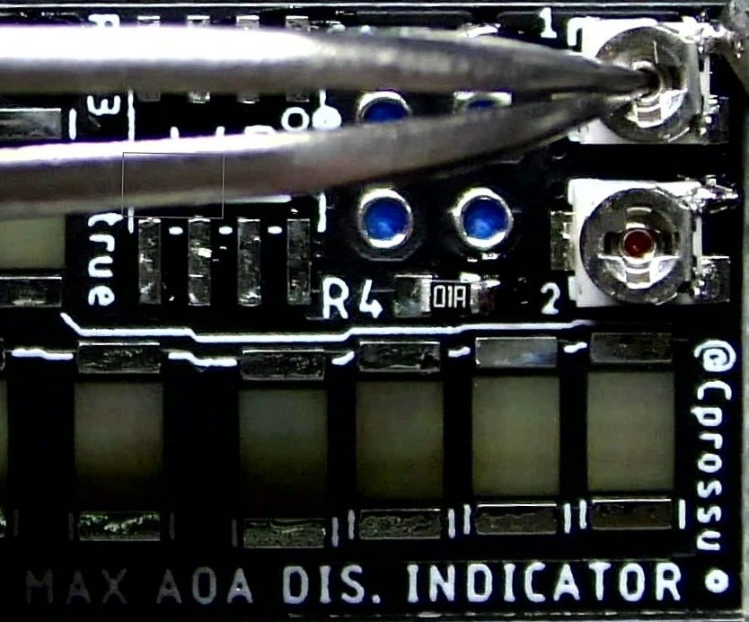
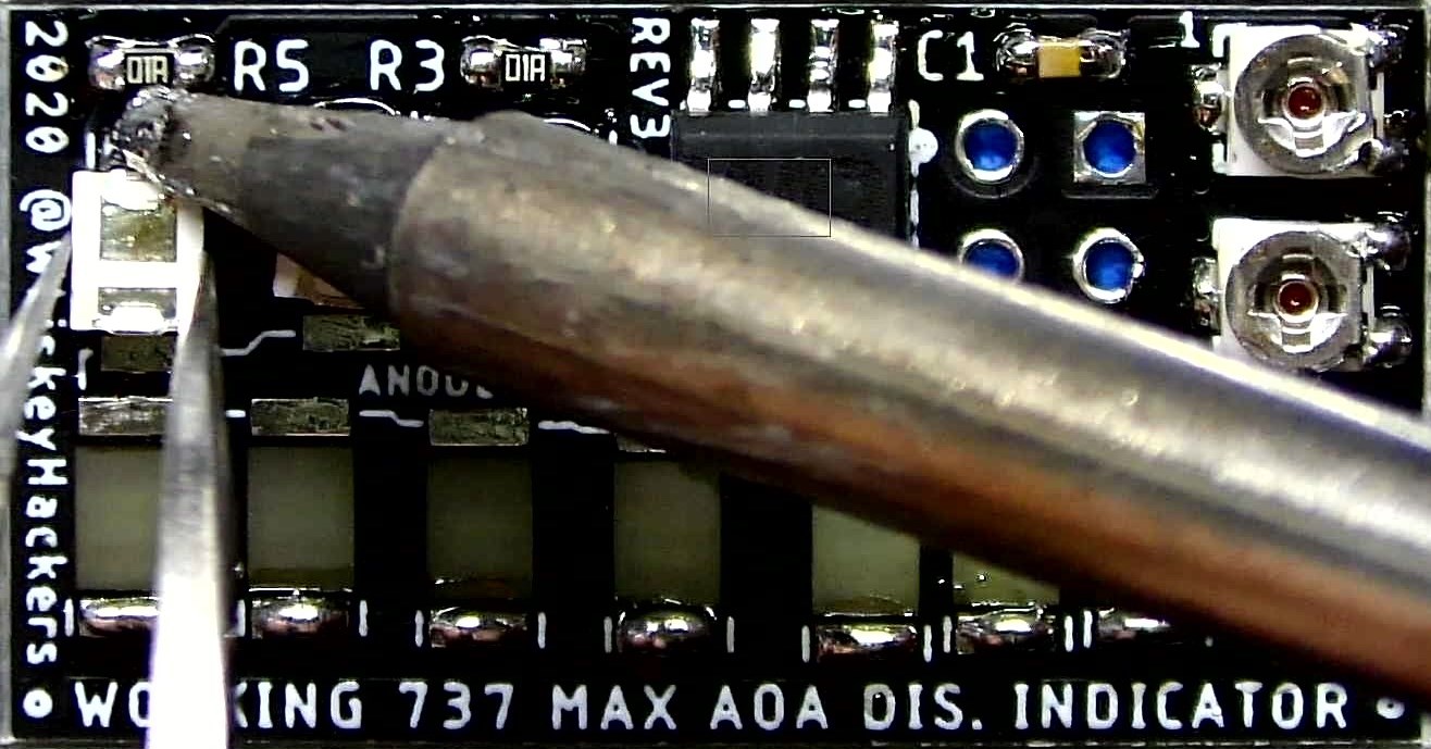
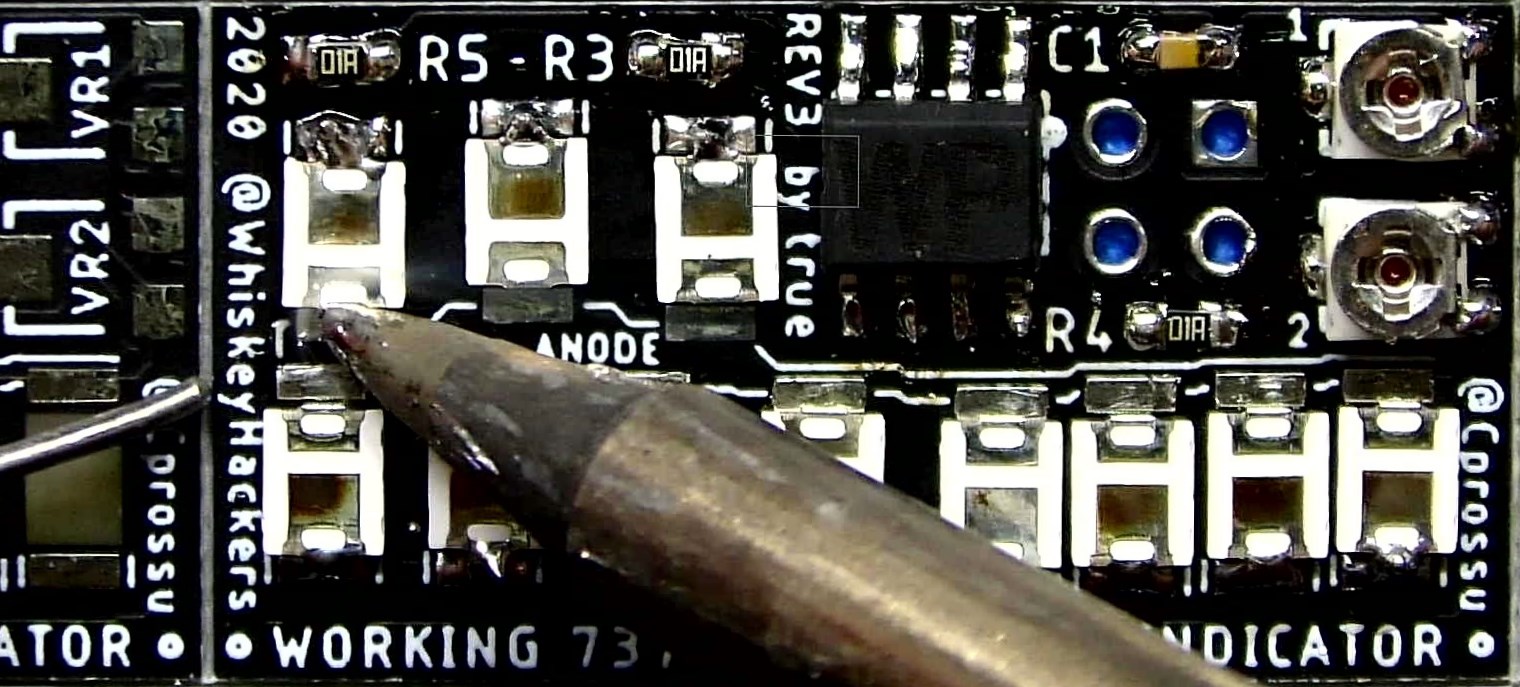
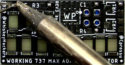
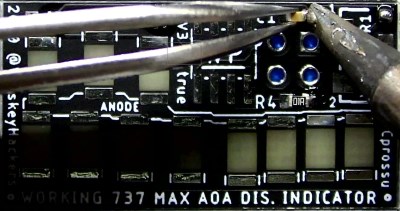
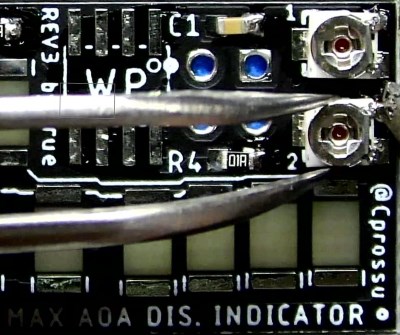
6. Solder top leg of SMD variable resistor. To get the VR flat, you can use tweezers as pictured.

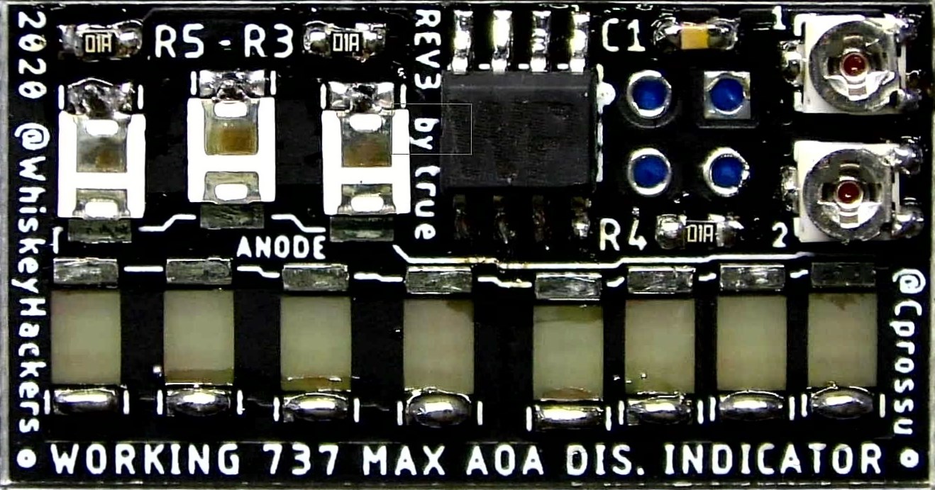
7. Solder the right lower pads of the variable resistors, followed by the left pads of all parts placed so far.

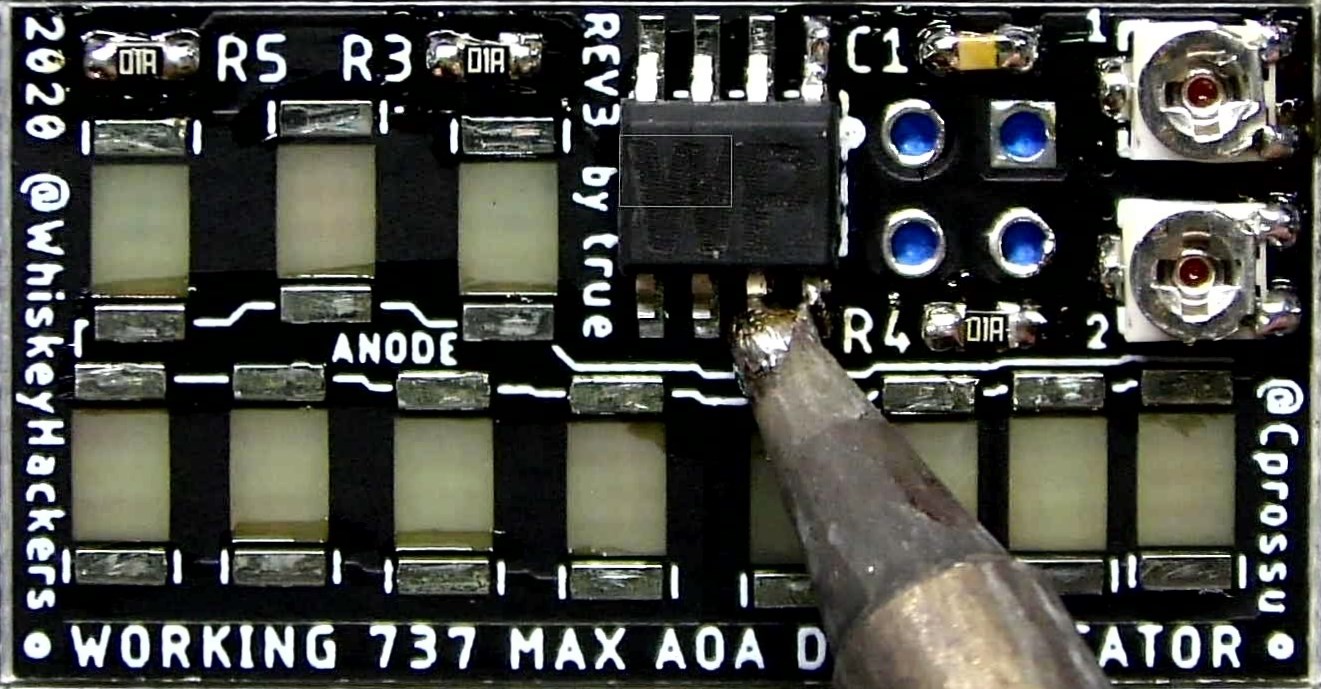
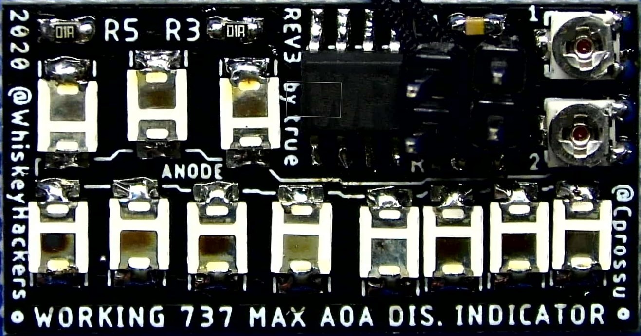
8. Solder the WP CHIP, maintaining correct orientation.

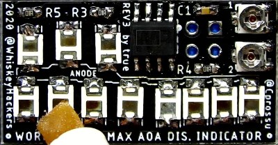
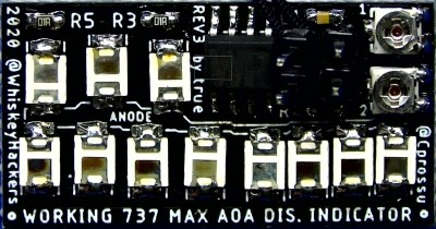
9.   Tin the upper portions of the upper LED pads, and the lower portions of the lower LED pads.
     A good technique is to place your solder wire on the pad, then quickly tap your iron to it.
     This should result in not burning all the flux, which will help in the following steps.
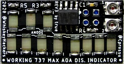
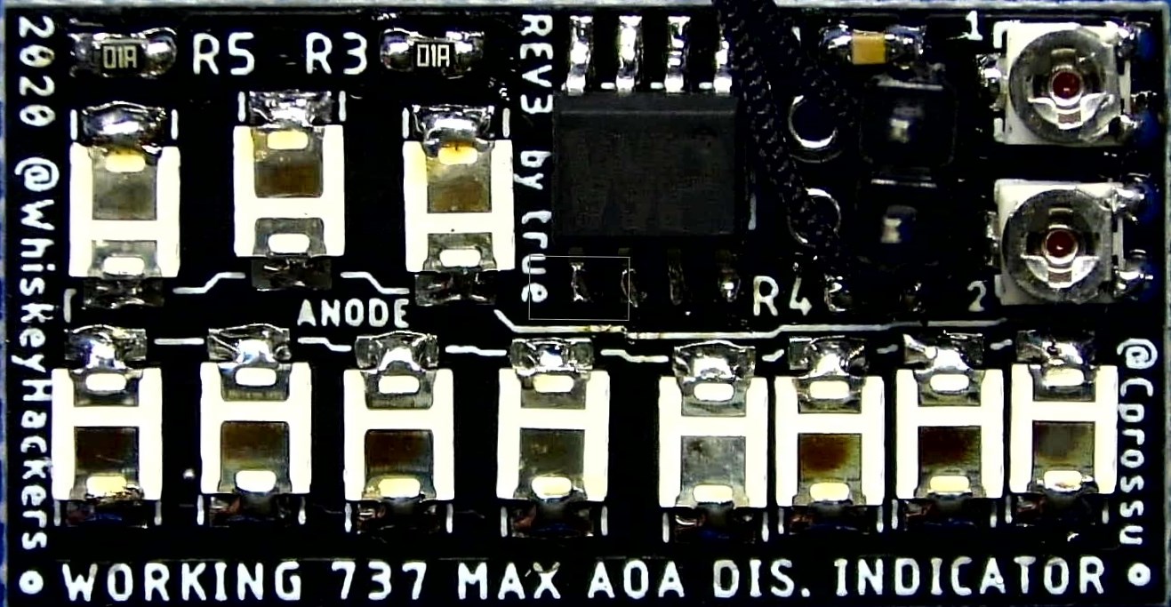
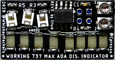
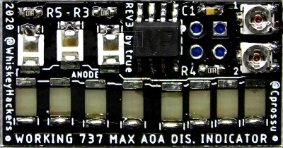
10.  Place a row of LEDs on the board. You can do top or bottom first, it doesn't matter.
     Orient the LEDs so the cathode (large side) points to the edge, and the anode (small side) points to the center.
11.  Tack the LEDs in place with the iron.
     Don't worry if the solder joint looks bad, just ensure the LED is tacked. We'll fix it later.
     Don't use too much pressure, or maintain heat too long, otherwise you may damage the LED.
     (This is why you were sent extra LEDs. With practice you shouldn't damage any.)

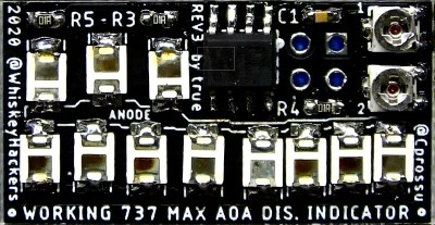
12. Follow steps 10-11 for the other row.
13.  Solder the anode connections of the LEDs.
     As before, don't use too much pressure, or maintain heat too long, otherwise you may damage the LED.

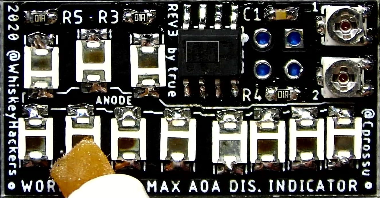
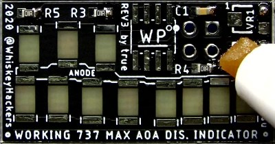
14. Apply flux to the top of the top row of LEDs, and to the bottom of the bottom row of LEDs.
15.  Using the soldering iron, tap the freshly fluxed pads of the LEDs to form a clean connection.
     Do not seek a perfect joint. Seek a cleanly connected, shiny joint. Heat will destroy the LED pads.
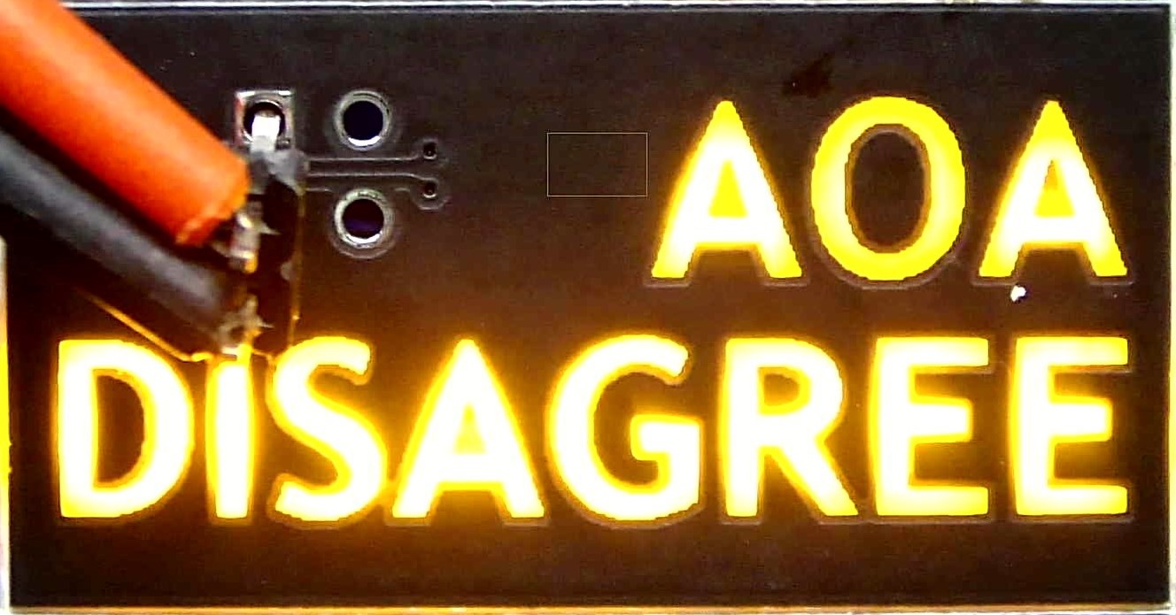
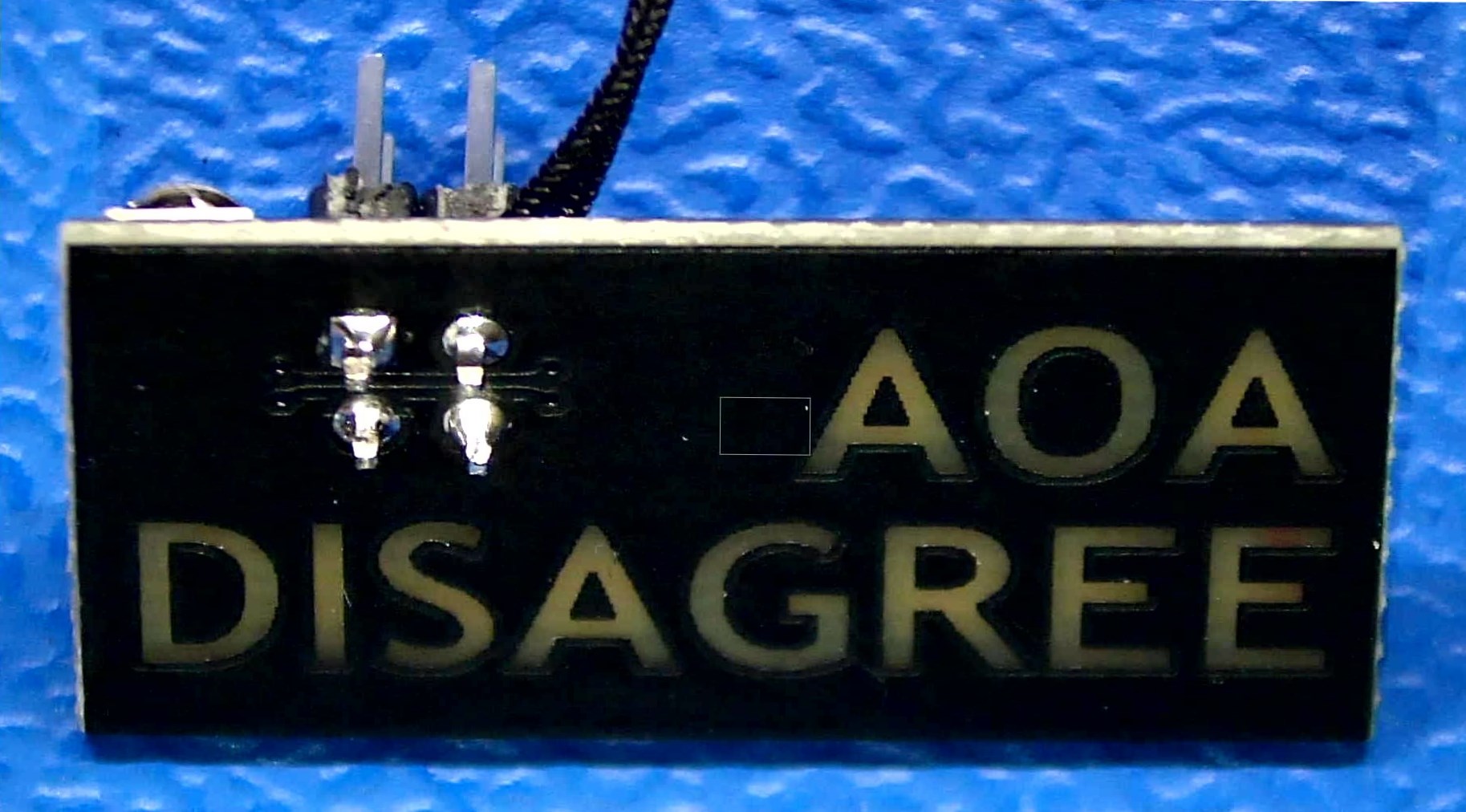
16. If you have a voltage source available, test the badge.
If you don't have a voltage source available, why are you making this?
In a pinch, you can use an addon header on a badge with pins inserted temporarily.
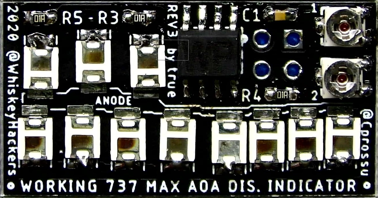
When powered, you should see a pattern that lights all LEDs.

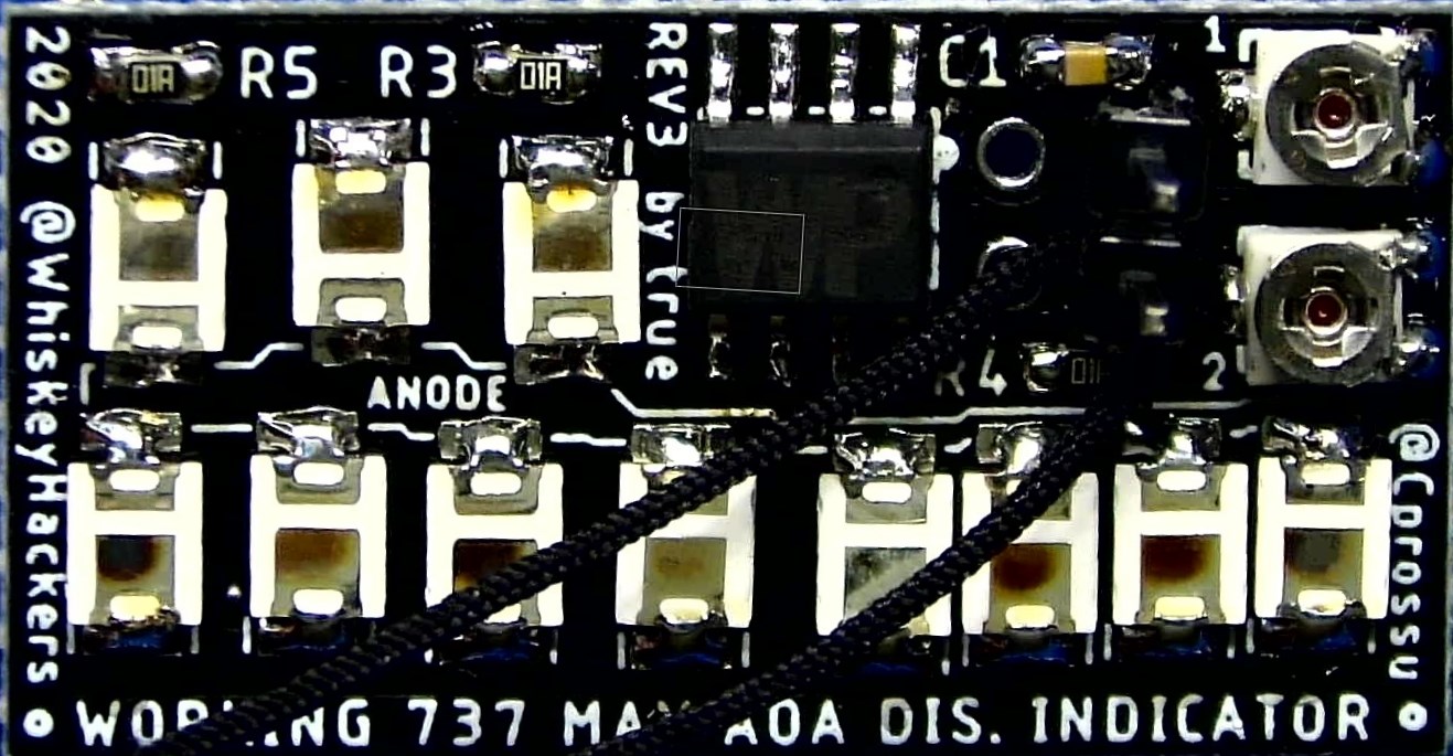
17a. If you don't wish to use the retention lanyard, solder the pin headers.
     Solder in vertical strips as shown. Use your skill to determine how to do this.
     Clean up with isopropyl alcohol. Assembly complete!
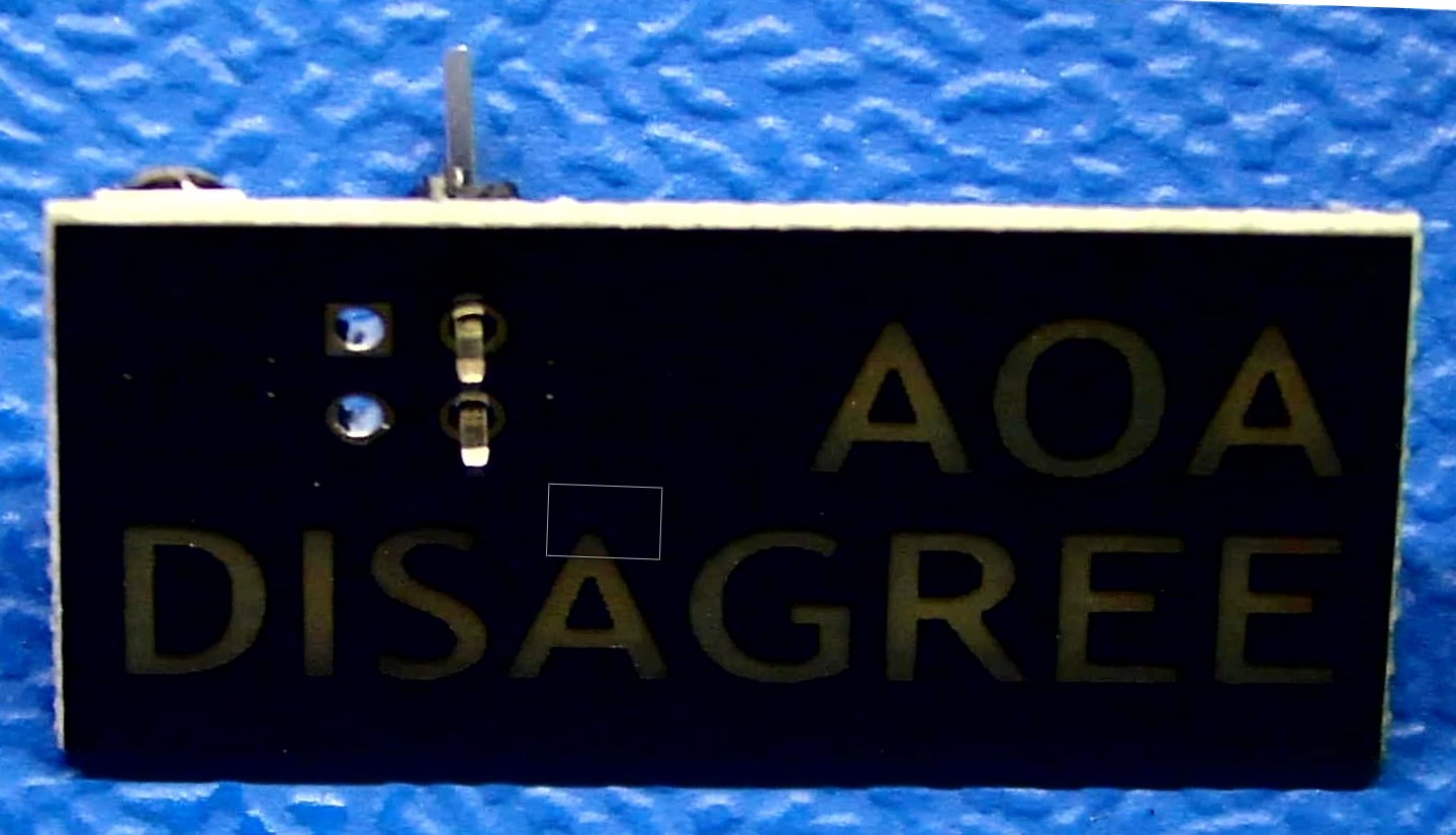
17b. If you wish to use the retention lanyard, it needs to be held under the soldered pin headers.
     The best method of attachment we've been able to devise is described and shown as follows.
     First, looking from the rear of the board, loop the rounded end of the lanyard through the bottom right header pin.
     The lanyard should be squished between the header and the board in the rear.
     Tack the header into place, adjust the lanyard to face toward the top of the board, then finish soldering into place.
18.  Add the second header, allowing the top of the lanyard loop to go over the top pin, and the bottom to go between pins.
     Solder the header into place. Assembly complete!

Thank you for your support, and good luck!